'unreal engine(언리얼 엔진 UE)' 카테고리의 다른 글
| 언리얼엔진 5 C++ (0) | 2024.04.03 |
|---|---|
| 언리얼엔진 설정 초기화 (0) | 2023.07.12 |
| 언리얼엔진 5 C++ (0) | 2024.04.03 |
|---|---|
| 언리얼엔진 설정 초기화 (0) | 2023.07.12 |
| 언리얼엔진 5 C++ 클랙스 삭제 (0) | 2024.04.03 |
|---|---|
| 언리얼엔진 설정 초기화 (0) | 2023.07.12 |
| git github 명령어 (0) | 2023.12.12 |
|---|---|
| Next.js 14 (0) | 2023.12.11 |
Git
git-scm.com
GitHub: Let’s build from here
GitHub is where over 100 million developers shape the future of software, together. Contribute to the open source community, manage your Git repositories, review code like a pro, track bugs and fea...
github.com
git init.git 하위 디렉토리 생성
git add README.md프로젝트 소개글 생
git status작업 디렉토리와 스테이징 영역 상태 확인
git add .현재 디렉토리의 모든 변경 내용을 스테이징 영역
$ git add <파일/디렉토리 경로>
$ git add -A
$ git add -p
git branch -M mainhttps://git-scm.com/book/en/v2/Git-Branching-Branch-Management
git remote -v

# origin  https://github.com/user/repo.git (fetch)
# origin  https://github.com/user/repo.git (push)
원격 저장소 연결 확인
git remote set-url origin https://github.com/user/변경할repo.gitgit remote set-url origin {변경할 원격 저장소 주소}
git push -u origin mainorigin 주소에 branch(main) 업로
-u 옵션 초기값 저장
.gitignore 파일 무시
https://docs.github.com/ko/get-started/getting-started-with-git/ignoring-files
Ignoring files(파일 무시) - GitHub Docs
GitHub에 체크 인하지 않으려는 파일을 무시하도록 Git을 구성할 수 있습니다.
docs.github.com
출처
| 리액트 풀코스 무료(2024) / React Full Course for free ⚛️ (2024) (0) | 2024.02.01 |
|---|---|
| Next.js 14 (0) | 2023.12.11 |
export default function Home() {
  return (
  <>
  </>
  )
https://nextjs.org/docs/getting-started/installation
Getting Started: Installation | Next.js
Create a new Next.js application with `create-next-app`. Set up TypeScript, styles, and configure your `next.config.js` file.
nextjs.org
https://www.youtube.com/watch?v=smAU6-ZdcoQ&list=RDCMUCvc8kv-i5fvFTJBFAk6n1SA&index=12
npx create-next-app@latest
What is your project named? my-app
Would you like to use TypeScript? No / Yes
Would you like to use ESLint? No / Yes
Would you like to use Tailwind CSS? No / Yes
Would you like to use `src/` directory? No / Yes
Would you like to use App Router? (recommended) No / Yes
Would you like to customize the default import alias (@/*)? No / Yes
What import alias would you like configured? @/*
npm run dev
https://www.youtube.com/watch?v=GFF3zgFS7Ug
export default function Home() {
  return (
  <>
    <h1>page</h1>
  </>
  )
html
<script type="module" src="index.js"></script>
Home.js
export function Home(){}
import {Home} form './Home.js'
export default function Home(){}
import Home from './Home.js'
무료 로티 애니메이션, 모션 그래픽을 위한 모든 플러그인과 도구를 한 곳에 - 로티파일즈/LottieFi
로티파일즈/LottieFiles는 오픈소스 애니메이션 포맷 로티를 제공하는 세상에서 가장 큰 무료 플랫폼입니다. 웹, iOS, 안드로이드, 윈도우를 위한 모션 그래픽 작업을 지원하는 플러그인과 툴을 통
lottiefiles.com
https://www.npmjs.com/package/react-lottie-player
react-lottie-player
Fully declarative React Lottie player. Latest version: 1.5.5, last published: 4 months ago. Start using react-lottie-player in your project by running `npm i react-lottie-player`. There are 63 other projects in the npm registry using react-lottie-player.
www.npmjs.com
Vercel: Build and deploy the best Web experiences with The Frontend Cloud
Vercel's Frontend Cloud gives developers the frameworks, workflows, and infrastructure to build a faster, more personalized Web.
vercel.com
| 리액트 풀코스 무료(2024) / React Full Course for free ⚛️ (2024) (0) | 2024.02.01 |
|---|---|
| git github 명령어 (0) | 2023.12.12 |
| C,C++ : 네임스페이스(namespace) (0) | 2023.08.04 |
|---|---|
| C,C++ : 비트(bit)연산 (0) | 2023.08.02 |
| C,C++ : 구조체 포인트 (0) | 2023.07.31 |
| C,C++ : 구조체 만들기(struct) (0) | 2023.07.31 |
| C,C++ : typedef 자료형에(구조체) 새 이름(별명) (0) | 2023.07.31 |
http://www.lcdwiki.com/2.4inch_Arduino_Display
2.4inch Arduino Display - LCD wiki
3 LCD_RS LCD bus command / data selection signal, low level: command, high level: data
www.lcdwiki.com
아두이노 Uno, Mega2560 등의 보드에 꽂아서 사용하는 컬러 터치 LCD입니다.
동봉된 터치펜으로 손가락보다 정밀한 입력도 가능하며 예제 소스코드로 손쉽게 구동할 수 있습니다.
MicroSD카드소켓이 있어 저장된 이미지 또는 데이터를 표시하는 등의 응용이 가능합니다.
추가 reset버튼이있어 기존 버튼을 가리더라도 불편이 없습니다.
※아두이노보드가 포함되어있지 않은 제품입니다.
화면크기 : 48.96mm×36.72mm(2.4inch)
전체크기 : 72.20mm×52.70mm
해상도 : 320×240 pixel (QVGA)
지원색상 : RGB
지원보드 : Arduino Uno
Arduino Due
Arduino Mega2560
Arduino Mega ADK
Arduino Leonardo
드라이버IC : ILI9341
화면 인터페이스 : 8bit parallel data bus
외부 인터페이스 : microSD 소켓
구성품 : TFT LCD 쉴드, 터치펜
첨부된 예제소스 중 일부는 이하의 라이브러리를 사용합니다.
https://github.com/JoaoLopesF/SPFD5408
※ (첨부파일 제외)상기 링크에서 다운로드 시 라이브러리 내 SPFD5408_TouchScreen.cpp 파일에서
return TSPoint(x, 1023 - y, z); -> return TSPoint(1105 - x, y - 40, z); 로 변경하시기 바랍니다.
※ (첨부파일 제외)상기 링크에서 다운로드 시 spfd5408_tftpaint.ino 예제
#define TS_MINX 125 -> #define TS_MINX 150
#define TS_MINY 85 -> #define TS_MINY 120
#define TS_MAXX 965 -> #define TS_MAXX 920
#define TS_MAXY 905 -> #define TS_MAXY 940
로 변경하시기 바랍니다.
https://www.devicemart.co.kr/goods/view?no=1377405
아두이노 2.4인치 컬러 터치 TFT LCD 쉴드 arduino 2.4inch Color Touch TFT LCD Shield
아두이노 Uno, Mega2560 등의 보드에 꽂아서 사용하는 컬러 터치 LCD입니다. 동봉된 터치펜으로 손가락보다 정밀한 입력도 가능하며 예제 소스코드로 손쉽게 구동할 수 있습니다. ※아두이노보드가
www.devicemart.co.kr
| 작화프로그램 (USART HMI / Nextion Editor) (0) | 2023.09.10 |
|---|---|
| SMD 전자소자 명칭 (0) | 2023.09.05 |
| GUI : Embedded Wizard (0) | 2023.08.15 |
| 3.5inch_ESP32-3248S035R/C (0) | 2023.08.14 |
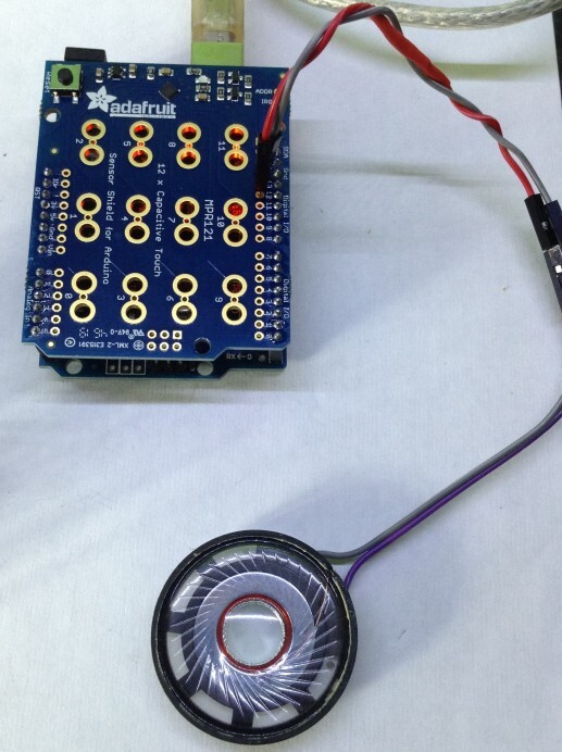
| D1 mini IOT / MPR121 (0) | 2023.08.08 |
https://diyelectromusic.wordpress.com/2020/08/25/arduino-mpr121-touch-piano/
Arduino MPR121 Touch Piano
This project uses on off-the-shelf capacitive touch shield or module to provide touch-sensitive pads for a 12 (recommended for beginners) to 48 (advanced) note “piano”. These are the …
diyelectromusic.wordpress.com
This project uses on off-the-shelf capacitive touch shield or module to provide touch-sensitive pads for a 12 (recommended for beginners) to 48 (advanced) note “piano”.
These are the key Arduino tutorials for the main concepts used in this project:
If you are new to Arduino, see the Getting Started pages.
The easiest modules to use are from Adafruit, so I suggest you take a look at:
As you can see one is a shield for the Arduino Uno with crocodile clip friendly connections. The other is a generic breakout board with headers for using with a solderless breadboard and any microcontroller of your choice.
For an alternative, if you search for MPR121 on popular auction sites or Chinese suppliers you will find a number of breakout boards that look very similar to the now discontinued Sparkfun Capacitive Touch Sensor Breakout board, again designed for use with solderless breadboards and any microcontroller you fancy. The one I found looks like this:

I have an Adafruit shield and several cheap ebay modules, so I’m basing the rest of this project around those.
Using a Single Module – 12 Inputs
By the far the simplest thing is to use one of these modules to provide 12 inputs. In the case of the Adafruit shield, just plug in the shield and you are ready to go!
In the case of the non-Adafruit modules, the following connections are required:
Arduino 3.3V      --- 3.3V or VIN
Arduino GND       --- GND
Arduino SDA or A4 --- SDA
Arduino SCL or A5 --- SCL
One key feature worth noting is that the MPR121 chip itself is a 3.3V device not 5V. The Adafruit boards include an on-board regulator which happily takes care of the power conversion. The non-Adafruit devices do not, they have to be powered from the 3.3V supply of the Arduino or you will damage the boards.
Now all the circuits and tutorials I’ve seen imply that as long as you power the module from the 3.3V pin of the Arduino, then you can link up SDA and SCL to the Arduino and it just works. But this means that you are using 5V logic at the Arduino end to talk to 3.3V logic at the MPR121 end. This might be ok – the MPR121 datasheet wasn’t very illuminating on the topic. In practice this does seem to work, but I don’t know for how long.
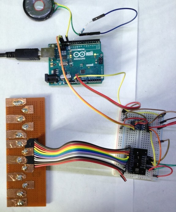
Extending to Multiple Modules – up to 48 Inputs
All of these modules use one of the built-in communication busses of the Arduino for communications – in this case the I2C interface (which stands for Inter-Integrated Circuit) which is a serial protocol using a data signal (SDA), a clock (SCL), power and ground. I’ll not go into the details of how I2C works here, but it is worth noting that every device connected to I2C has an address to uniquely identify it to the Arduino.
All of these boards allow you to choose one of four addresses. By default, its address is 0x5A (that is 5A in hexadecimal). By linking the ADDR (or ADD) pin to one of 3.3V, SDA or SCL it is possible to change the default and choose 0x5B, 0x5C or 0x5D. This means a single microcontroller than support up to 48 capacitive touch inputs using these modules.
I have to say, the Adafruit modules are very simple to change address – just patch the ADDR pin to one of 3.3V, SDA or SCL, or leave it unconnected (it is linked to GND by default). The Sparkfun based boards are more complication in that they need you to cut a track between a jumper that will default to connecting ADD(R) to ground or you risk shorting the board.
At the very least, I found that the address selection using SDA or SCL doesn’t work when using 5V levels.
The solution, if you are using one of these boards with no on-board regulator, is to use a bi-directional level shifter that takes 5V on one side and converts it to 3.3V on the other. This can be used for the SDA/SCL signal pins. Mine looks like this.

IMPORTANT: Recall that there is a jumper that has to be cut to allow ADDR to be linked to another pin for second and subsequent boards. For my module, this is on the underside as shown here.
To resort back to the default setting, the link between ADDR and GND must be re-established either by a solder joint here or linking the external pin to GND.
The final circuit for me, supporting several of these MPR121 breakout boards looks like this.
In summary, the Adafruit modules are much easier to use, in fact the shield is very easy to setup! The Adafruit module is easier if you plan to use several modules linked together, but the non-Adafruit modules can be made to work ok and can be found very cheaply online if you look.
Regardless of which module you chose, Adafruit have provided an Arduino library for the MPR121 which works really well with any module based around the MPR121 chip. You need to install it using the library manager – just search for MPR121 and you’ll see “Adafruit_MPR121”. The provided example code is a quick way to test that your module is working using simple “one-module” connections as described above.
I have taken the basic code from the Arduino Touch Piano and updated it to use the Adafruit library.
Now, I want to support up to four of these modules, which will therefore support up to 48 capacitive inputs – that is enough for four octaves! So I’ve used the ToneMelody pitches.h file once again to define frequencies for the Arduino tone() function for the range C3 up to B6.
The Adafruit library links up to the MPR121 using a Adafruit_MPR121 programming object, so to support four devices I include four of these objects (called cap1 to cap4).
// It is possible to have up to four of these connected.
// But it needs the "addresses" to be set correctly.
Adafruit_MPR121 cap1 = Adafruit_MPR121();
Adafruit_MPR121 cap2 = Adafruit_MPR121();
Adafruit_MPR121 cap3 = Adafruit_MPR121();
Adafruit_MPR121 cap4 = Adafruit_MPR121();
In the code I look for devices at each of the four I2C bus addresses (0x5A, 0x5B, 0x5C, 0x5D) and record any I find using the “numcaps” variable. Note that I actually use the lowest four bits to record which modules are found, so the first module (at 0x5A) is indicated by the lowest bit (i.e. numcaps = 1) and the others by bits 2, 3 and 4 (or values of 2, 4, and 8 respectively). This means I am able to work out which of the boards are present later in the code by examining the bits of numcaps.
Then in the main loop() function I scan any found devices (by examining the bits of numcaps) and read the 12 inputs for each one.
 // Loop through all possible cap devices
for (int c=0; c<4; c++) {
  // Get the currently touched pads for all found cap devices
  uint16_t currtouched;
  if (numcaps & (1<<c)) {
    switch (c) {
    case 0:
      currtouched = cap1.touched(); break;
    case 1:
      currtouched = cap2.touched(); break;
    case 2:
      currtouched = cap3.touched(); break;
    case 3:
      currtouched = cap4.touched(); break;
  }
...
I then use this as the basis for which note to play via the tone() function. The code will always “play” the highest note detected and will keep playing until either the note changes or no notes are detected.
If you turn on the Arduino serial monitor, there is a continual feed of debug output that tells you which sensors have been read at any one time which can be handy for fault finding.
The standard 220Ω resistor-to-speaker circuit is added from pin 12 and GND for the audio output to complete the module.
These modules make it relative easily to do a “diy” version of the Instant Touch Music. With a bit of work it can be seen that many more inputs are possible. These modules certainly take much of the complication of capacitive sensing away from the code compared to doing it all by hand.
Now that I’ve introduced the idea of communicating with off the shelf modules using one of the built-in IO busses from the Arduino, there are many more modules that have musical potential that could be looked at.
Kevin

JAOJINGCHI
-중국 내수 버전
제품 모델명 : TJC
https://tjc1688.com/index.html
http://filedown.tjc1688.com/USARTHMI/USARTHMIsetup_latest.zip
http://wiki.tjc1688.com/download/usart_hmi.html#id1
VK4PK - Nextion HMI LCD Touch Screen
Nextion HMI LCD Touch Screen Contents: The Nextion and TJC HMI Display Units Specification Nextion Editor on Linux TJC4024T032_011 Chipsets Chip Level Components by Stuart VK4MSL Installing The TJC Editor and English language patch Nextion Models Reference
www.lyonscomputer.com.au
USARTHMIsetup_0.57_English_language_patch.zip
1.09MB
실행 중인 편집기를 닫고 패치의 압축을 푼 다음 HMIFORM.dll 및 hmitype.dll 두 파일을 Windows 폴더 "Program Files (x86)\USART HMI\"에 복사하고 편집기를 시작합니다. 현재 버전에 대한 업데이트를 선택하지 마십시오. 패치가 자동으로 적용되며 편집기는 영어로 표시됩니다. 링크를 클릭하면 중국어 페이지로 연결될 수 있다는 점에 유의하세요.
-클리벌 버전
제품 모델명 : NX
https://nextion.tech/nextion-editor/#_section1
https://nextion.tech/datasheets/
| 2.4" TFT LCD SHIELD : 2.4inch Arduino Display (0) | 2023.09.14 |
|---|---|
| SMD 전자소자 명칭 (0) | 2023.09.05 |
| GUI : Embedded Wizard (0) | 2023.08.15 |
| 3.5inch_ESP32-3248S035R/C (0) | 2023.08.14 |
| D1 mini IOT / MPR121 (0) | 2023.08.08 |
| 형태 | 명칭 | 특징,설명 |
 |
저항 | |
 |
트랜지스터 | |
  |
콘덴서, 커패시터 |
https://c0mp.tistory.com/963 - 충전/방전을 반복함으로써 불안정한 전원을 잡아주기 위해 사용 - 직류를 통과시키지 않고 교류만 통과시키게 함 - 다이오드와 정류회로를 구성하여 교류를 직류로 만듬 - 콘덴서의 충전시간을 이용해서 펄스의 시간지연을 만듬 - 저항과 함께 구성하여 여러 신호들 중에서 저주파 또는 고주파 신호만을 꺼냄 - 노이즈를 제거하기 위한 방법으로 사용 - IC(집적회로)의 안정된 작동을 위해 사용. |
 |
퓨즈 | |
 |
다이오드 | |
| 2.4" TFT LCD SHIELD : 2.4inch Arduino Display (0) | 2023.09.14 |
|---|---|
| 작화프로그램 (USART HMI / Nextion Editor) (0) | 2023.09.10 |
| GUI : Embedded Wizard (0) | 2023.08.15 |
| 3.5inch_ESP32-3248S035R/C (0) | 2023.08.14 |
| D1 mini IOT / MPR121 (0) | 2023.08.08 |
VSCode 설치 : https://code.visualstudio.com/
Visual Studio Code - Code Editing. Redefined
Visual Studio Code is a code editor redefined and optimized for building and debugging modern web and cloud applications. Visual Studio Code is free and available on your favorite platform - Linux, macOS, and Windows.
code.visualstudio.com
PlatformIO 설치 : (https://youtu.be/PYSy_PLjytQ)
LVGI 사이트 : https://lvgl.io/
LVGI 설명서: https://docs.lvgl.io/master/
| float h = 1.123; lv_label_set_text_fmt(ui_Label2, "%.1f", h); lv_conf.h 데이터 변경 # define LV_SPRINTF_DISABLE_FLOAT 1 // 프린트에서 프로트 사용함. https://forum.lvgl.io/t/lv-label-set-text-fmt-outputting-f-on-display-and-not-the-actual-text/4164 |
https://www.embedded-wizard.de/
Simplify Your GUI Development - Embedded Wizard
Simplify Your GUI Development Lean. Versatile. Scalable. Fast. DOWNLOAD FREE EDITION GUI for Your Embedded Platform Embedded Wizard is TARA Systems’ embedded GUI technology that enables you to create platform-independent and high-performance graphical us
www.embedded-wizard.de
| 작화프로그램 (USART HMI / Nextion Editor) (0) | 2023.09.10 |
|---|---|
| SMD 전자소자 명칭 (0) | 2023.09.05 |
| 3.5inch_ESP32-3248S035R/C (0) | 2023.08.14 |
| D1 mini IOT / MPR121 (0) | 2023.08.08 |
| ESP32 S2 Mini / 마이크로 파이썬 설정 방법 (0) | 2023.08.07 |
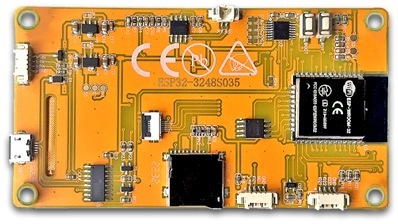
https://macsbug.wordpress.com/2022/10/02/esp32-3248s035/
ESP32-3248S035
ESP32-3248S035R/C motherboard ORG. 2022.09.16 . …
macsbug.wordpress.com
ESP32-3248S035R/C motherboard ORG. 2022.09.16
. rev 1. 2022.09.19
. rev 2. 2022.09.22
3.5″ 320×480 SPI ST7796 with Resistive Touch Panel XPT2046
価格:
2314円 送料込 ($16.13)。輸送期間:14日。
3.5″ 320×480 SPI ST7796 with Capacitive Touch Panel GT911
価格:
2733円 送料込 ($19.04)。輸送期間:未到着。
低価格で ESP32, LCD Display等が1つの基板でできています。
販売店:Sunton Store
輸送期間;14日で Aliexpressの中では早い方でした。
サイズ:Displayは 75x50mmでカードサイズ。全体は 101.5×54.9mm。

| 無印のメイクパレット・S (990円) に入ります。 |
.
.
構成:
1. ESP32 with TELEC(211-161007) : 内部 4MB(32Bit) Flash
2. 外部 4MB(32Mbit) Flash memory, winbond 25Q32JVSlQ
3. LCD ( ST7789 ) with Touch ( XPT2046 抵抗膜方式)
4. Expanded IO x 2
_ P3 ( GND, GPIO_35, GPIO_22, GPIO_21)
_ CN1 ( GND, NC, GPIO_21, 3.3V)
5. SD SLOT ( Micro SD ) : CS=GPIO_5
6. RGB LED ( MHP5050RGBDT )
_ RED=GPIO_4, GREEN=GPIO_17, BLUE=GPIO_16
7. CDS ( GT36516 ) : CS=GPIO_34
8. EXT Power Conn : P1 ( VIN, TX, RX, GND )
9. Audio OUT(Audio amp SC8002B) : GPIO_26
_ P4 SPEAK(1=VO1, 2=VO2)
10. P1 Power Supply Bace Connector(VIN, TX, RX, GND)
11. 付属:Touch pen, 4pin External connector cable, USB Cable。
資料:
– 購売店に ESP32-3248S035Rのdownload linkがあります。重要です。
– Display Libraryは LovyanGFX (ST7789, XPT2046, SPI2_HOST)で動作。
– 3.5inchは 大きく 操作性良く とても見やすい大きさです。
– ボタンやキーボード等を自由に配置でき 物理スイッチは不要です。
.
.
開発環境 :
HARD : ESP32_3248S035R ( R = Resistor Touch の意味 )
– Display : 3.5″ 320×480 SPI ST7796 LCD Touch XPT2046
Dev environment : Arduino IDE 1.8.19
– Board Manager : arduino-esp32 2.0.3-RC1
– Board : “ESP32 Dev Module”
– Upload Speed : “460800” (Mac), “921600” (Win)
– CPU Frequency : “240MHz (WiFi/BT)”
– Flash Frequency : “80MHz”
– Flash Mode : “QIO” or “DIO”
– Flash Size : “4MB (32Mb)”
– Partition Scheme : No OTA (2MB APP/2MB SPISSF)”
– Core Degug Level : “None”
– PSRAM : “Disabled”
– Arduino Runs On : “Core 1”
– Events Run On : “Core 1”
– Pord : “dev/cu.wchusbserial14240”
_ memo :
_ CH340C の為 Upload Speed は Mac と Win では 異なります。
_ LovyanGFX Touch cfg.pin_int = 36; Touchが動作しない場合は -1 にします。
Library : LovyanGFX
.
.
追記:SPI接続 設計ミス:2022.09.22
ESP32-2432S028 , ESP32-3248S035 の U4 外部 4MB Flash memoryについて。
U2 ESP32-WROOM-32 は 内蔵 4MB Flash です。そして外部Memoryとして
U4 4MB Flash Memory 8Pin W25Q32JV があります。
Flashは SPI接続で VCC以外のPinは全て(CS,DI, DO, WP,CLK, HOLD,GND)共通。CSもです。
マルチサブモードやマルチスレーブにはなっていません。
よって U4のCS並列接続は設計ミスと判断しています。
不具合事例:Arduino IDEでUP LOAD(書き込み)時にエラーが発生し書き込み不可。
_ Flashの破損。他、不可解な現象が発生します。
現象:UP LOAD不可。
Flashが壊れます。
原因:U2内部FlashとU4外部FlashのCS,DI,DO共通によりFlashが重複。
対策:
U4 Flash を取り除きます。
詳細:以降の解説 19 を参照ください。
.
.
記事修正:2022.09.19
UP LOAD に関し 設計ミスが判明し修理致しました。
.
.
Down Load:DL後 pdf(_.pdf)を削除しzipを解凍します。
Down Load : Life_Game_ESP32_3248S035.zip
Down Load : LVGL802_demo_ESP32_3248S035.zip
Down Load : Maze_generator_ESP32_3248S035.zip
Down Load : MovingCircles_ESP32_3248S035.zip : obj_count 100 =11 FPS,
Down Load : Raytrace_ESP32_3248S035.zip
Down Load : Test_PDQ_ESP32_3248S035.zip
Down Load : uncannyEyes_ESP32_3248S035.zip
Down Load : Tetris_ESP32_3248S035.zip:revision:Bug修正。2022.09.19
.
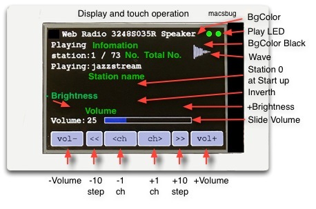
Down Load : WebRadio_ESP32_3248S035_SP.zip:revision:2022.09.19
- Web Radio ESP32-3248S035 Speaker版:
- P4 SPEAK 端子にSpeakerを接続し音を再生出来ます。
- 8Ω 2W 40x5mm Speaker と間に100Ωを接続します。過電流防止です。
- ダイソー330円スピーカは 直接接続でき 充分聞ける音質です。
- デジタル Web Radio ESP32-2432S028-I2S方式との比較はノイズが僅か入ります。
- 局の廃止や受信不良が発生する場合があります。
.
.
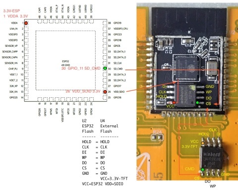
部品レイアウト:配置、信号、ピンは色分けしてあります。

以下のPDF図面は 拡大表示が可能と文字検索が可能です。
配線や設計、改造時に便利です。
ESP32-3248S035R_PCB_Layout
.
GPIO Pin Assign:部品とGPIO表です。
1. GPIO39 は 未配線。
2. LCDとTouchの SCLK(14), MOSI(13), MISO(12) は 共有。(薄緑)
3. Touch Resistive CS と Touch Capacitive SDA は 共有。(薄紫)
4. P3 IO21 と CN1 IO21 と Capacitive Touch INT は 共有。(薄橙)
.
| Cds | R21 |
| GPIO | 34 |
| Audio AMP | U5 |
| GPIO | 26 |
| LED1 | RED | GREEN | BLUE |
| GPIO | 4 | 16 | 17 |
| U4 Flash | HOLD | WP | CLK | DI | DO | CS |
| GPIO | SD2 | SD3 | CLK | SD1 | SD0 | CMD |
| GPIO | 9 | 10 | 6 | 8 | 7 | 11 |
| LCD SPI | LED | RST | DC(RS) | SCLK | MOSI | MISO | CS |
| GPIO | 27 | EN(-1) | 2 | 14 | 13 | 12 | 15 |
| Touch SPI Resistive | INT(IRQ) | SCLK | MOSI | MISO | CS |
| GPIO | 36 | 14 | 13 | 12 | 33 |
| Touch I2C Capasitive | INT(IRQ) | SCL | SDA | RST |
| GPIO | 21 | 32 | 33 | 25 |
| SD | DATA2 | VSS | VDD | CLK (CLX) |
MOSI (CMD) |
MISO (DAT0) |
CS(CD) |
| GPIO | 3V3 | GND | 3V3 | 18 | 23 | 19 | 5 |
.
Connector:
| P3 | GND | IO35 | IO22 | IO21 |
| CN1 | GND | NC | IO21 | 3V3 |
| P1 | VIN | TX | RX | GND |
| P4 | VO1 | VO2 |
.
Touch Panel:
1. Touch Calibration:
_ 電源ONでタッチキャリブレーションが始まり四隅の入力が終了で
_ Calibration の値を取得できます。Arduino IDEのSerial Monitorに
_ uint16_t calData[5] = { 200, 3559, 194, 3741, 3 };
_ tft.setTouch(calData);
_ とか表示され calData として使用できます。
_ Library TF-eSPI で setup に記載して使用できます。
2. LGFXで 以下の値でも結構まともにセンスします。
_ cfg.x_min = 360; , cfg.x_max = 4200;
_ cfg.y_min = 180; , cfg.y_max = 3900;
| Touch | x_min | x_max | y_min | y_max |
| LGFX | 360 | 4200 | 180 | 3900 |
.
3. タッチパネル使用可能条件:
_ Arduino IDE : CPU Frequency : “240MHz” と LGFX cfg.pin_int = -1;
_ Arduino IDE : CPU Frequency : “160MHz” と LGFX cfg.pin_int = 36;
_ スケッチ;Loop中に長いdelayを入れない事。参考:Tetris
.
解説:
- ESP32やESP32ボード共通の情報も含まれます。
1. ESP32 : 内部 4MB(32Bit) Flash
- esptool.py flash_id の表示。
|
1
2
3
4
5
6
7
8
9
10
11
|
Detecting chip type... ESP32
Chip is ESP32-D0WD-V3 (revision 3)
Features: WiFi, BT, Dual Core, 240MHz, VRef calibration in efuse, Coding Scheme None
Crystal is 40MHz
MAC: 40:22:d8:57:f1:fc
Uploading stub...
Running stub...
Stub running...
Manufacturer: ef
Device: 4016
Detected flash size: 4MB
|
.
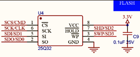
2. U4 External FLASH Memory 4MB(25Q32):
- 外部 4MB(32Mbit) Flash memory, winbond 25Q32JVSlQ
- 拡張用のFLASH 4MB です。CS=GPIO_11。
- 3V 32M-BIT SERIAL FLASH MEMORY WITH DUAL, QUAD SPI
- External Flash : Start Address 0x3F40_0000 End 0x3FF8_0000
- 4MB (4194303バイト):詳細:ESP32 Technical Reference Manual
_ 参考:ESP-WROOM-32の外部フラッシュメモリにアクセスする
.
3. LCD Touch MISO:Arduino IDE の setup に必要な設定。
- このボードでは GPIO_39 Input は使用されていません。
- GPIO_39 は WiFI使用時に Pulseが発生します。(画像:左)
- 対策:以下を記載するとPulseは無くなります。 (画像:右)
- 原因:ESP32チップのバグです。
|
1
2
3
|
void setup() {
WiFi.begin();
WiFi.setSleep(false);
|
- GOIO 36 Input
- 同様にESP32のバグで GPIO36も短いスパイクが出るという情報。
- GPIO39, GPIO36 もPulseにより接続部品が壊れる事を想像します。
- 対策:adc_power_acquire(); を setupの先頭に記述します。
- 結果:GPIO36 および GPIO39 のグリッチは除去されます。
|
1
2
|
void setup() {
adc_power_acquire();
|
| WiFi.begin() | WiFi.setSleep(false) |
.
4. 配線図とボードの差異:
- 部品タイプの変更。
- 配線図:R1, R3, R12, R13, R14, R18, SMD 103 10KΩ。
- ボード:R1, R3, R12, R13, R14, R18, SMD 01C 10KΩ。
–
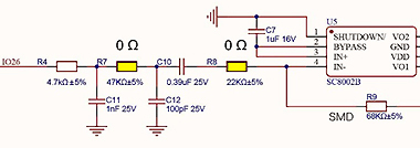
- Audio Circuit : GAIN の変更。回路図を参照してください。
- 配線図:R7 = 47KΩ。ボード:R7 = 0Ω
- 配線図:R8 = 22KΩ。ボード:R8 = 0Ω
- 部品タイプの変更:R9 SMD 68E (68KΩ)
- ESP32-2432S028 と比較し GAIN の変更。
- Speaker で聞く分には大差ないです。
- 回路図:ESP32-3248S035-LCM-V1.1.jpg
- 回路図:ESP32-2432S028-LCM.jpg
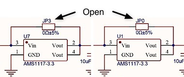
–
- JP0, JP3 端子
- 配線図:0Ω。ボード:Open
- JP0:LDO=AMS1117, 3.3V-TFT:3.3Vdc 4mVac
- JP3:LDO=AMS1117, 3.3V-ESP:3.3Vdc 3mVac
.
5. P1, P3, CN1, P4 Extender Connector Cable:
| No. | Nomen | Purchase | Price |
| 1 | P,P3,CN1 Extender . Cable Connector . HC-1.25-4PWT |
EFEF Store . JST1.25, 10cm, Single head, 4P . 価格:20個283円 |
15円 |
| 2 | P4 Extender . Cable Connector . JST_1.25_2P |
EFEF Store . JST1.25, 10cm, Single head, 2P . 価格:10個99円。 |
10円 |
.
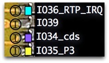
6. INPUT ONLY GPIO:入力専用GPIOの把握。
- GPIO_36 (RTP_IRQ), GPIO_39 , GPIO_34 (cds), GPIO_35 (P3) は
- INPUT ONLYです。使用時や回路変更時に注意してください。
.
.
7. 共有(Commn) GPIO 21:使用時の注意。
- GPIO_21 は P3 , CN1 , CTP_INT と共有です。
.
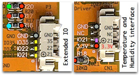
- Capacitive Touch CTP_INTは R25(0Ω)経由で基板上にパターンがあります。
- R25(0Ω)は 未装着でOpen になっています。
.
8. LCD GPIO_12 (TFT SDO ) R24 (0Ω)は 未装着。
- ESP32 GPIO_12 は 起動モード設定に使用される為
- Low にする必要があります。
.
.
.
.
9. 電源:3.3Vは 2系統の電源になっています。
- USB 5VdcからD1 Diodeを経由し LDO AMS1117で3.3Vdc。
- D1 1N5819W Diode の出力は 4.6Vdc 17mvacです。
- 3.3V は 2つのLDOにより 3.3V-ESP と 3.3V-TFT が作られます。
.
.
10. P1 Power Supply Base Connector:使用時の注意。
- USB接続時 VIN には Q1 FET から 4.6V 17mvacが出ています。
- Q1 FET Gate が GNDの為 Q1 は ON です。
- 使用時に検討ください。
- Diode D1 1N5819W pdf:Vf = 0.32V(0,1A), Vf = 0.45V(1.0A), - 5.0-0.45=4.6V
.
.
11. P4 SPEAK と Speaker:スピーカー接続方法。
- P4 コネクターへ 外部スピーカを接続できます。
- ダイソーの330円スピーカーに接続でき充分聞ける音です。
- スピーカーの径が大きいと音質が向上します。
- スピーカー単体の接続は 追加抵抗値が 100Ω程度必要です。
- 直接 4Ω や 8Ω の Speakerを接続しますと電流が流れすぎ
- 3.3V電源が低下し ESP32が停止します。
- 例;8Ω 2W 40x5mm Speaker に 100Ω を直列に接続します。(画像:左)
.
12. ESP32 EN 時定数:
- R1(10KΩ) と C4(0.1μ) で 時定数 τ(タウ) は 47μsec です。
- 47μsecは ESP32 の起動には 仕様を満たした安全な値です。
.
13. ESP32 Revision:Revision 3 です。
- Serial port /dev/cu.wchusbserial14240
- Detecting chip type… ESP32
- Chip is ESP32-D0WD-V3 (revision 3)
- Revision 1 は 不具合versionですので, 3 で良かったです。
.
14. 速度:
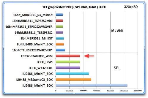
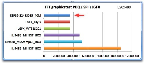
- 3248S035は SPI接続で Parallel 8/16bit との差が解ります。
- 同じ 320×480 の中で 最高速の中に入っています。
- 部品の選択が大きな要素です。
- LovyanGFX使用により高速表示が実現します。
- ILI9486 や M5Stamp C3 は遅いです。
.
.
.
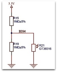
15. R21:GT36516 Photoresistor:Cdsの動作範囲。
- 以下の特性ですので 動作範囲を把握して使用します。
- R21 Cds は GPIO_34 (Input)へ接続されています。
- テスターで対GND電圧と抵抗値測定。
- 暗くする :150mVdc , 抵抗値=25KΩ
- 明るくする;部屋の蛍光灯:20mVdc , 抵抗値=5.5KΩ。窓の光:16mVdc
- プログラム:
- analogSetAttenuation(ADC_0db); // 0dB(1.0倍) 0~800mV
- pinMode(34, ANALOG);
- 計測:Serial.printf(“%d[mV]\n”, analogReadMilliVolts(34) );
- 計測結果;部屋を暗くする:230mVdc.。明るくする;75mVdc
- 指で遮蔽した程度では 変化は少なく 明暗の差が必要です。
.
.
16. LCD Library:
- LovyanGFX を使用し 設定は以降に示します。
- LovyanGFXは 高速である事と FONTが多数用意されている事や
- 漢字が容易に使用できます。
.
17. 速度とタッチセンス
- 速いMPUやLGFXは 表示速度が速くチラツキなく見やすくなります。
- Tetris の Loop は 25msecで表示を繰り返しています。
- ブロックが落下する速度は 25msec が見やすい速度の為です。
- 遅いM5Stackでは 安易に Loop に 25msec delay を入れていました。
- 速度が速くなると delay方式は タッチセンスしない為 使用できません。
- delayを使用しない方法でのプログラムが必要になります。
.
18. PCBは カードサイズ:ケースの製作方法。
- カードサイズの為 市販のカードケースや化粧ケースが使用可能です。
- 加工は伴いますが 3Dプリンターは不要で 綺麗に仕上がります。
| 無印良品:メイクパレット・S 111x71x15mm ( 990円 )。 位置を決めて 穴を開けます。 USBの位置は 右か左側に決めます。 USBコネクターの位置を十分検討。 |
養生テープを取り付け 穴を開け アセトンを流し込むと 鏡の両面テープ(4x8mm)が取れます。 カッターやヤスリで窓を開けます。 |
.
| ケースの高さに合う ナイロンネジ(M3 5-8mm)を取り付けます。 P4 SPEAK Connector : JST_1.25_2P と 販売店:EFEF store:価格:10個99円。 8Ω 2W 40x5mm Speaker + 100Ω を取り付けます。 ーーーーーーーーーーーーーーーーーーーー P1, P4, CN1 Connector:HC-1.25-4PWT 販売店:EFEF store:価格:20個283円。 |
.
| 隙間がないように仕上げます。 ステレオミニジャックを取り付けて ダイソースピーカに接続も出来ます。 |
表示具合です。 右の配線は 黒テープ等で処理。 光造形3Dプリンタより綺麗です。 |
.
.
19. U4 SPI 接続:設計ミス。追記:rev 2. 2022.09.22
- U2 ESP32 内蔵 4MB Flash と U4 外部 Flash 4MB 8pin W25Q32JV の配線は
- VCC を除き全て(CS,DI, DO, WP,CLK, HOLD,GND)共通です。CSもです。
- 判断の根拠は マルチサブモードやマルチスレーブには なっていません。
- CSが並列なら DI,DO信号は直列接続にする必要があります。
- DI,DO信号が並列なら CS信号は 別にする必要があります。
- 回路図 及び 実際の配線は 上記の基本の様になっていません。
- 設計者は並列と言い 何の為に 並列にしているか根拠が不明です。
- 設計者に2回 お聞きしても問題ないとの返事で 根拠は述べていませんでした。
- さらに 設計者は並列の制御方法は知らないと述べていました。
現象:UP LOAD不可。
Flashが壊れます。
原因:U2内部FlashとU4外部FlashのCS並列によりFlashが重複。
処置:
U4 Flash 4MBを散り外します。図面を参照ください。
- ハンダゴテで片側4つの端子に並列に熱を加えピンセツトで上に持ち上げます。
- 片側が外れましたらもう片側の端子に熱を加え取り除きます。
- ハンダゴテがない場合 ニッパーやカッター等でピンを全て切り取り外します。
- 特にGNDだけを外す様な 更なるな不具合を発生させる方法はしない事。
- ICの仕様にない接続をしないと言う事です。
- U4は 並列で何の役にも立っていませんので取り外し時に壊れても良いでしょう。
- 実施後は アセトンかアルコールで基板をクリーニングします。
- この件は 私の判断ですので 各自で責任をお持ちください。
-処置:U4取外しでもダメな場合は ESP32内蔵 4MB Flashを交換します。
- この場合 金属の蓋を開け 修理改造になりますので TELECは無くなります。
–
PDF:画像が見え難い場合は PDF を参照ください。S028_S035_SPI_480s
.
2個並列に書き込んだFlashは どうなるか?
- U2内部FlashとU4外部Flashが 正しく書き込まれている場合と
- 書き込まれていない場合の4通りができます。
- U4外部Flashを外すと
- 1. U2内部Flashが正しく書き込まれていると 以前のスケッチがそのまま動きます。
- 2. U2内部Flashが正しく書き込まれていないと 動作せず表示しません。
これは この並列接続は 間違っている事を示しています。
;
- 正しく書き込まれていないFlashを混ざて動かすと奇妙な現象が発生します。
- Arduino IDEで書き込み回数が(50〜200回とか)多くなると顕著に発生します。
- 例として GPIO_27使用不可,タッチ操作不可,書き込み不安定,書き込不可,MD5エラー,
- U2内部Flash破損(esptoolでeraseしても不可)(最悪),等々が発生しました。
- esptool.py での erase は esptool.py erase_flash でなく以下が良いです。
- ただし この基板は これだけの問題でなく CH340C の問題があります。
|
1
2
3
4
5
6
7
8
|
実施前 以下で確認。
esptool.py chip_id
esptool.py flash_id
erase 実施。
esptool.py erase_region 0x10000 0x1000
実施後 以下で確認。
esptool.py chip_id
esptool.py flash_id
|
;
MD5エラーは 書き込み回数の多い M5Stackでも発生する現象です。
- 対策は esptool.pyで Flashをeraseすると治ります。
- S028,S035の場合 取り外し後に U2内部Flashが正しく書き込まれていないと
- 2,3回 MD5エラーで書き込みができなくなりますが その後は書き込みが
- 出来る様になります。
- Espressif SystemsのSPI Flashを読むと 私には 極めて難しい事が書かれており
- 奥義もある様で自分の判断が正しいのか疑問に包まれます。
- eraseで 治った様に見えましたが その後も 再び MD5 error が発生。
- 対策は Auto Program で無く Manualで書き込んでいます。
_ Manual program :
_ USB Re-Connect , Boot + Reset Switch, Reset Open, Boot Open です。
_ 経験的ですが CH340C はこの現象が多いです。
.
基板不具合: rev 1. 2022.09.18
タッチ操作の不完全とUP LOAD の2つの不具合に時間を要しました。
最初は時々 発生。その後 かなりの歩度で不具合発生。
投稿後にも不具合が再発し不具合部品の交換を実施。
1. 不具合:Touch IC U3 XPT2046 x,y 入力は良いが pin-11 IRQ Output 無し。
- 原因:XPT2046 IRQ Output Pin-11 の不良。
- 処置:U3 XPT2046 を交換し IRQ OUTPUT は正常になる。
- メモ:U3 Pin-9,10 は GND です。2つあることは重要で 不十分な GNDは
- HI=3.3V が 2.5V とかになり “1” であるはずの Logicが “0” になります。
2. 不具合:USB接続切れが発生する。書き込み時にエラーメッセージ発生し書き込めない。
- 「 A fatal error occurred: Serial data stream stopped: Possible serial noise or corruption.」
- 「 A fatal error occurred: MD5 of file does not match data in flash!』も発生する。
- 原因:U2 ESP32内のFlash 4MB。
- 処置:Flash 4MBを16MBに交換し書き込みは正常になる。
- メモ:esptool で 内蔵 Flash Memory を消去し 治った様に見えましたが治らず。
_ esptool.py erase_region 0x1000 0x8000
_ memoryの不具合は タッチ操作が不安定にもなりました。
_ CPU Frequency : “240MHz (WiFi/BT)” : LGFX cfg.pin_int = -1; と
_ CPU Frequency : “160MHz (WiFi/BT)” : LGFX cfg.pin_int = 36; なら動作する
_ と言う 摩訶不思議な現象が発生しました。
2. CH340C: Arduino IDE Upload Speed は
- Mac で “460800” 。 Win で “921600” です。
- それぞれの OSで過去の速度は遅く 時と共に改善されました。
- Mac で “921600” にしますと MD5 error が多発します。
その後、モニターしていますが 再び MD5 error が発生。
対策は Auto Program で無く Manualで書き込んでいます。
_ USB Re-Connect , Boot + Reset Switch, Reset Open, Boot Open です。
.
.
LIbrary Lovyan GFX 使用により多くの事が容易にできます。
Lovyan GFX 設定:
_ Display:ST7789 SPI:SPI2_HOST , SPI3_HOST 又は HSPI_HOST
_ cfg.freq_write : Max 40000000 ( 40MHz )
_ Touch:XPT2046 SPI:SPI2_HOST , SPI3_HOST 又は HSPI_HOST
_ Touch:cfg.pin_int = 36; Touchが動作しない場合は -1 にします。
_ Arduio IDE :
_ tft.setRotation(1); // USB Right
_ tft.setRotation(3); // USB Left
//----------------------------------------------------------------------
// https://github.com/lovyan03/LovyanGFX/blob/master/examples/HowToUse/2_user_setting/2_user_setting.ino
class LGFX : public lgfx::LGFX_Device{
  lgfx::Panel_ST7796  _panel_instance;
  lgfx::Bus_SPI       _bus_instance;
  lgfx::Light_PWM     _light_instance;
  lgfx::Touch_XPT2046 _touch_instance;
//----------------------------------------------------------------------
public:LGFX(void){{            // バス制御の設定を行います。
  auto cfg = _bus_instance.config();// バス設定用の構造体を取得します。
                               // SPIバスの設定
  cfg.spi_host   = SPI2_HOST;  // 使用するSPIを選択 (VSPI_HOST or HSPI_HOST)
  cfg.spi_mode   = 0;          // SPI通信モードを設定 (0 ~ 3)
  cfg.freq_write = 40000000;   // 送信時のSPIクロック(最大80MHz,80MHzを整数割値に丸め)
  cfg.freq_read  = 16000000;   // 受信時のSPIクロック
  cfg.spi_3wire  = false;      // 受信をMOSIピンで行う場合はtrueを設定
  cfg.use_lock   = true;       // トランザクションロックを使用する場合はtrueを設定
  cfg.dma_channel=  1;         // 使用DMAチャンネル設定(1or2,0=disable)(0=DMA不使用)
  cfg.pin_sclk   = 14;         // SPIのSCLKピン番号を設定 SCK
  cfg.pin_mosi   = 13;         // SPIのMOSIピン番号を設定 SDI
  cfg.pin_miso   = 12;         // SPIのMISOピン番号を設定 (-1 = disable) SDO
  cfg.pin_dc     =  2;         // SPIのD/C ピン番号を設定 (-1 = disable) RS
  // SDカードと共通のSPIバスを使う場合、MISOは省略せず必ず設定してください。
  _bus_instance.config(cfg);   // 設定値をバスに反映します。
  _panel_instance.setBus(&_bus_instance);// バスをパネルにセットします。
  }
  {                            // 表示パネル制御の設定を行います。
  auto cfg = _panel_instance.config();// 表示パネル設定用の構造体を取得します。
  cfg.pin_cs          =    15; // CS  が接続されているピン番号(-1 = disable)
  cfg.pin_rst         =    -1; // RST が接続されているピン番号(-1 = disable)
  cfg.pin_busy        =    -1; // BUSYが接続されているピン番号(-1 = disable)
  cfg.memory_width    =   320; // ドライバICがサポートしている最大の幅
  cfg.memory_height   =   480; // ドライバICがサポートしている最大の高さ
  cfg.panel_width     =   320; // 実際に表示可能な幅
  cfg.panel_height    =   480; // 実際に表示可能な高さ
  cfg.offset_x        =     0; // パネルのX方向オフセット量
  cfg.offset_y        =     0; // パネルのY方向オフセット量
  cfg.offset_rotation =     0; // 回転方向の値のオフセット 0~7 (4~7は上下反転)
  cfg.dummy_read_pixel=     8; // ピクセル読出し前のダミーリードのビット数
  cfg.dummy_read_bits =     1; // ピクセル外のデータ読出し前のダミーリードのビット数
  cfg.readable        = false; // データ読出しが可能な場合 trueに設定
  cfg.invert          = false; // パネルの明暗が反転場合 trueに設定
  cfg.rgb_order       = false; // パネルの赤と青が入れ替わる場合 trueに設定 ok
  cfg.dlen_16bit      = false; // データ長16bit単位で送信するパネル trueに設定
  cfg.bus_shared      = false; // SDカードとバスを共有 trueに設定
  _panel_instance.config(cfg);
  }
  { // バックライト制御の設定を行います。(必要なければ削除)
  auto cfg = _light_instance.config();// バックライト設定用の構造体を取得します。
  cfg.pin_bl = 27;             // バックライトが接続されているピン番号 BL
  cfg.invert = false;          // バックライトの輝度を反転させる場合 true
  cfg.freq   = 44100;          // バックライトのPWM周波数
  cfg.pwm_channel = 7;         // 使用するPWMのチャンネル番号
  _light_instance.config(cfg);
  _panel_instance.setLight(&_light_instance);//バックライトをパネルにセットします。
  }
  { // タッチスクリーン制御の設定を行います。(必要なければ削除)
  auto cfg = _touch_instance.config();
  cfg.x_min      = 360;    // タッチスクリーンから得られる最小のX値(生の値)
  cfg.x_max      = 4200;   // タッチスクリーンから得られる最大のX値(生の値)
  cfg.y_min      = 180;    // タッチスクリーンから得られる最小のY値(生の値)
  cfg.y_max      = 3900;   // タッチスクリーンから得られる最大のY値(生の値)
  cfg.pin_int    = -1;     // INTが接続されているピン番号, TP IRQ 36
  cfg.bus_shared = true;   // 画面と共通のバスを使用している場合 trueを設定
  cfg.offset_rotation = 3; // 表示とタッチの向きのが一致しない場合の調整 0~7の値で設定
  // SPI接続の場合
  cfg.spi_host = SPI2_HOST;// 使用するSPIを選択 (HSPI_HOST or VSPI_HOST)
  cfg.freq = 1000000;      // SPIクロックを設定, Max 2.5MHz, 8bit(7bit) mode
  cfg.pin_sclk = 14;       // SCLKが接続されているピン番号, TP CLK
  cfg.pin_mosi = 13;       // MOSIが接続されているピン番号, TP DIN
  cfg.pin_miso = 12;       // MISOが接続されているピン番号, TP DOUT
  cfg.pin_cs   = 33;       // CS  が接続されているピン番号, TP CS
  _touch_instance.config(cfg);
  _panel_instance.setTouch(&_touch_instance);  // タッチスクリーンをパネルにセットします。
  }
  setPanel(&_panel_instance);// 使用するパネルをセットします。
  }
};
LGFX tft; // 準備したクラスのインスタンスを作成します。

//=====================================================================
.
感想:
価格:この構成で 2314円 は 超低価格です。
- 部品単価を踏まえ低価格に工夫されています。
- 個別の部品を計算すると 作るより購入した方が安いです。
- M5Stack 1台分の価格 6125円で 2台半も購入できます。
- 低価格は 気楽に電子工作ができます。
基板:インターフェースを追加すると良く出来ている事が解ります。
- GPIOやコネクター配線の変更が容易で 自由に改造できる様になっています。
- Schematicやレイアウトを見ると良く考察された基板です。
- 数ある ESP32ボードの中で 唯一 外部 Flash memory があり活用できます。
内部 Flash と 外部 Flash Memory:
- 初めて見る U4 外部 Flash Memoryが基板上で見れます。
- 購入時 U4 Flash は ESP32 Flash の外付けかと勘違いしていました。
- esptool.py flash_id では 4MB を表示。
- U4 Flash を外しても 購入時の LVGL DEMO は 動作しています。
- つまり ESP32 は 内部 Flash 4MB です。
- 確認の為に 販売店(開発者)に お聞きした所 ESP32 は 内部4MB,
- U4 は拡張用の4MBとの事。でした。
設計ミスの件:FLASH並列接続。
- 店(設計者)に 連絡したところ 「問題ない」との返事。
- 対し 私のボードはFlashが壊れ書き込めない事実。
- 仕様書や電気的にあり得ないSPI接続ですが それには答えずでした。
- FLASHは 並列接続と答え 使用方法は経験が無いとの返事。
- 尚、S045の販売数は さほどにはなっていません。
CH340C:UP- LOAD できない。CH340Cは 採用しないで下さい。
- M5Stack や TTGO は CH340Cは 採用していません。
- CP2102, CP2104, 最近では CH9102を採用しています。
- これは CH340G, CH340C の問題がある事を示しています。
- Arduino IDEで Auto Progできず、Manual ならできる。
- 原因追及していますが確実な所が不明です。
- Mac を使用していますが Mac と Win では Driver が異なります。
- 予想としては 昔からある CH340C の Hard に加え Driverの未完成です。
- CH340CをCP2102 に交換すれば 判明するでしょう。
- この件は 課題とします。
Touch:以下の場合があります。
- CPU Frequency : “240MHz (WiFi/BT)” と LGFX cfg.pin_int = -1; で動作。
- LGFX cfg.pin_int = 36; では 動作しない場合があります。
ポイント:
- 基本的な構成を備えながら 最も重要なポイントは 価格です 。
- ESP32-3248S035 や ESP32-24328S028 は 製品の中で
- コストメリットは 1番で これに対抗できるボードは 無いでしょう。
- これまで多くの基板を試してきましたが 作るよりも安いです。
- 作る時間をプログラム開発に活用できます。
- 2020年7月に販売された ESP32-24328S028R は
- 2022.09.16 に 730 Ordesr を達成しています。祝!
- M5Stackより 遥かに安い。
- 販売数の要因は 1に低価格で 2に基本的な構成の基板であるからと判断しています。
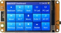
- openHASP:
- 海外では 購入して直ぐ openHASP を使用している人がいます。
-
購入トラブル:ESP32-3248S035C を注文しましたが届きません。
- 原因は 私のミスで届かない内に受領のボタンを押してしまいました。
- 店に連絡しましたが 送らないとの返事。サービスはとても悪いです。
- ESP32-3248S035C には GT911の問題点があると思い注文しましたが
- 手に入らずになりました。
- 連続して購入する気は無くなりました。
How do I correctly make the SD Card work for image widgets on an ESP32 Dev Kit with LVGL v.8.3?
Description What MCU/Processor/Board and compiler are you using? ESP 32 Devkit on Arduino IDE What LVGL version are you using? 8.3 What do you want to achieve? Setup File system to be able to use an image on an SD Card for LVGL widgets What have you tried
forum.lvgl.io
https://registry.platformio.org/libraries/rzeldent/esp32_smartdisplay
rzeldent/esp32_smartdisplay: LVGL driver for Sunton ESP32 TFT display boards
LVGL driver for Sunton ESP32 TFT display boards
registry.platformio.org
https://thinkanother.tistory.com/9
[EPS32/memory] 플래시 메모리가 부족할 때 해결법
[EPS32/memory] 플래시 메모리가 부족할 때 해결법 보통 많이 사용하는 모델로는 ESP32-WROOM-32로 개발 키트에 많이 적용된 모델입니다. 이 모델에는 4BM 플래시 메모리가 있습니다. 하지만 코드를 짜서
thinkanother.tistory.com
| SMD 전자소자 명칭 (0) | 2023.09.05 |
|---|---|
| GUI : Embedded Wizard (0) | 2023.08.15 |
| D1 mini IOT / MPR121 (0) | 2023.08.08 |
| ESP32 S2 Mini / 마이크로 파이썬 설정 방법 (0) | 2023.08.07 |
| CD74HC4067 / 74HC595 (0) | 2023.08.04 |
https://www.wikidebrouillard.org/wiki/Item:Capteur_Capacitif_MPR121
Item:Capteur Capacitif MPR121 — Wikidebrouillard
Capteur Capacitif MPR121 Le mpr121 est capteur tactile capacitif disposant de 12 broche capacitives 1EUR (€) Description longue Caractéristiques Ce module de haute précision possède 12 boutons tactiles et supporte la communication I2C. Il peut être f
www.wikidebrouillard.org
| GUI : Embedded Wizard (0) | 2023.08.15 |
|---|---|
| 3.5inch_ESP32-3248S035R/C (0) | 2023.08.14 |
| ESP32 S2 Mini / 마이크로 파이썬 설정 방법 (0) | 2023.08.07 |
| CD74HC4067 / 74HC595 (0) | 2023.08.04 |
| 네오픽셀 (0) | 2023.08.03 |
ESP32 S2 mini 마이크로 파이썬 설정 방법
1. 파이썬 설치 https://www.python.org/
2. Thonny 설치 https://thonny.org/
3. ESP32 S2 mini DFU 모드 설정
-0번 버튼을 누르고 있습니다.
-리셋 버튼을 누릅니다.
-연결음이 들리면 0번 버튼을 놓습니다.
4.Thonny [도구] > [옵션] >[인터프린터]에서 Install or update MicroPyhon 클릭한다.
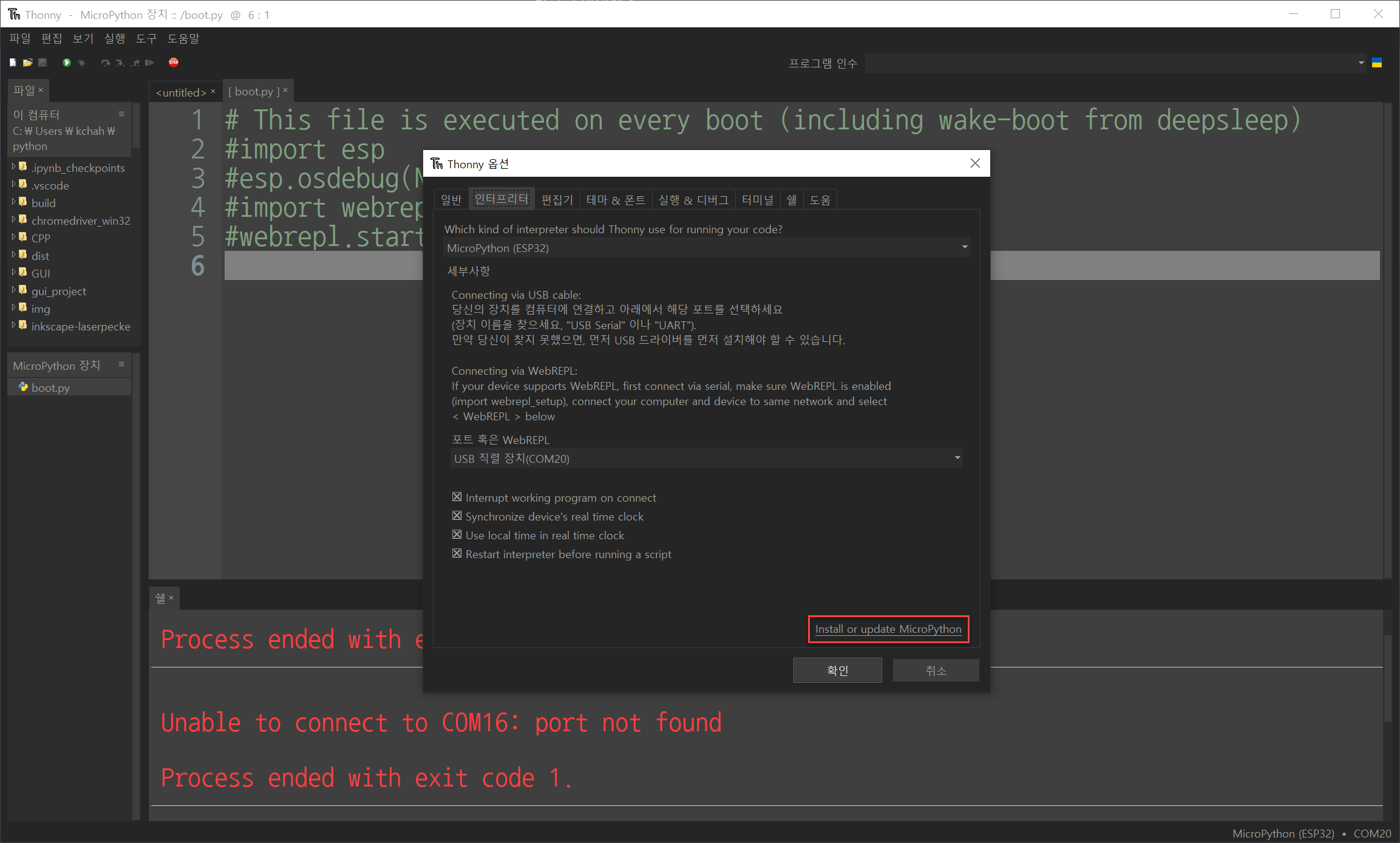
5.ESP32 firmware installer에서 Erase flash before installing(설치하기 전에 플래시 지우기) 해제한다.
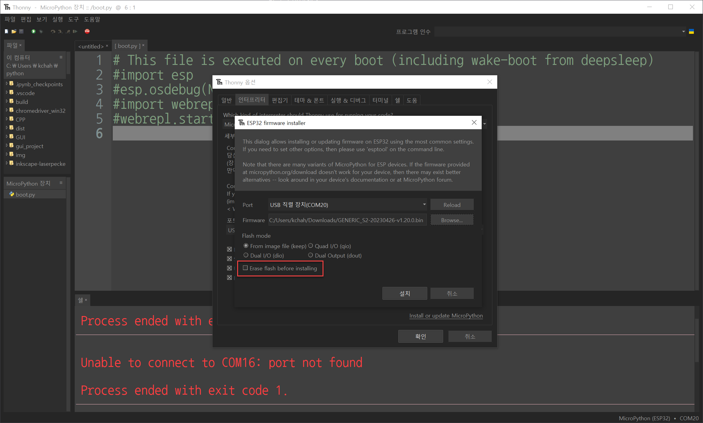
6. 설치 버튼을 크릭해서 설치를 진행한다.
7. 설치가 완료되면 ESP32 S2 mini 리셋 버튼을 누릅니다. (USB 연결음 및 COM 변경됨.)
-문제 해결 방법공장 초기화하고 다시 진행한다.
https://learn.adafruit.com/adafruit-esp32-s2-feather/factory-reset
참고 자료들
https://www.wemos.cc/en/latest/tutorials/s2/get_started_with_micropython_s2.html
Get started with MicroPython [S2 series] — WEMOS documentation
Flash MicroPython firmware The boards were already flashed micropython firmware. If they lost firmware or you need lastest firmware, you can flash MicroPython firmware by yourself.
www.wemos.cc
https://micropython.org/download/?mcu=esp32s2
MicroPython - Python for microcontrollers
MicroPython is a lean and efficient implementation of the Python 3 programming language that includes a small subset of the Python standard library and is optimised to run on microcontrollers and in constrained environments.
micropython.org
https://www.youtube.com/watch?v=2EuiAgvsOqw&t=21s&ab_channel=TURFPTAx
https://www.esp32.com/viewtopic.php?t=15222#p58448
esp32-s2 usb driver - ESP32 Forum
Postby DitroniX » Thu Apr 30, 2020 4:35 pm Having now populated some prototype designs using the ESP32-S2-WROOM, all display the same issue with lack of Windows 10 driver, and on different PCs. This occurs when going into programming mode ready for flashi
www.esp32.com
https://learn.adafruit.com/adafruit-esp32-s2-feather/factory-reset
ESP32 S2 mini 공장초기화
Adafruit ESP32-S2 Feather
What's Feather-shaped, has an ESP32-S2 WiFi module, a STEMMA QT connector for I2C devices, and lots of Flash and RAM memory for your next IoT project? The ESP32-S2 Feather! Check out all the details in this guide.
learn.adafruit.com
| 3.5inch_ESP32-3248S035R/C (0) | 2023.08.14 |
|---|---|
| D1 mini IOT / MPR121 (0) | 2023.08.08 |
| CD74HC4067 / 74HC595 (0) | 2023.08.04 |
| 네오픽셀 (0) | 2023.08.03 |
| Arduino Touch Sensor MPR121 (0) | 2023.08.02 |
/*
#include <iostream>

using namespace std;

int n;
void set();

namespace doodle {
	int n;
	void set();
	namespace google {
		int n;
		void set();
	}
}

int main() {
	::set();
	doodle::set();
	doodle::google::set();

	cout << ::n << endl;
	cout << doodle::n << endl;
	cout << doodle::google::n << endl;
}

void ::set() {
	n = 10;
}

void doodle::set() {
	n = 20;
}

void doodle::google::set() {
	n = 30;
}
*/

#include <iostream>

int n;
void set() {
	n = 10;
}

namespace doodle {
	int n;
	void set() {
		n = 20;
	}
	namespace google {
		int n;
		void set() {
			n = 30;
		}
	}
}

int main() {
	using namespace std;
	using namespace doodle;

	::set();
	doodle::set();
	google::set();

	cout << ::n << endl;
	cout << doodle::n << endl;
	cout << google::n << endl;
}| C++, CPP (OOP) (0) | 2023.10.19 |
|---|---|
| C,C++ : 비트(bit)연산 (0) | 2023.08.02 |
| C,C++ : 구조체 포인트 (0) | 2023.07.31 |
| C,C++ : 구조체 만들기(struct) (0) | 2023.07.31 |
| C,C++ : typedef 자료형에(구조체) 새 이름(별명) (0) | 2023.07.31 |


http://bbangpower-blog.blogspot.com/2021/03/74hc595.html
[아두이노] 74HC595 시프트 레지스터 연동
PLC, Factory Automation
bbangpower-blog.blogspot.com
| D1 mini IOT / MPR121 (0) | 2023.08.08 |
|---|---|
| ESP32 S2 Mini / 마이크로 파이썬 설정 방법 (0) | 2023.08.07 |
| 네오픽셀 (0) | 2023.08.03 |
| Arduino Touch Sensor MPR121 (0) | 2023.08.02 |
| NEW Arduino Uno R4 Boards - Minima & WiFi / 아두이노 우노 R4 미니머 & 와이파이 (0) | 2023.07.31 |
https://learn.adafruit.com/adafruit-neopixel-uberguide/arduino-library-use
Adafruit NeoPixel Überguide
NeoPixels are “intelligent” full-color RGB LEDs that can be controlled and chained from a single microcontroller pin. This guide presents an overview of NeoPixel products, along with tips for building and powering projects of all shapes and sizes.
learn.adafruit.com
| ESP32 S2 Mini / 마이크로 파이썬 설정 방법 (0) | 2023.08.07 |
|---|---|
| CD74HC4067 / 74HC595 (0) | 2023.08.04 |
| Arduino Touch Sensor MPR121 (0) | 2023.08.02 |
| NEW Arduino Uno R4 Boards - Minima & WiFi / 아두이노 우노 R4 미니머 & 와이파이 (0) | 2023.07.31 |
| ESP32 VS ESP8266 (0) | 2023.07.27 |
https://blog.naver.com/PostView.naver?blogId=yuyyulee&logNo=221079465686
[아두이노 강좌] 52. Bit 연산 (1) - &(AND)
※ 비트 연산에 대해 정확히 이해하고 있는 분들은 이번 포스팅을 건너뛰어도 좋다. 하지만 조금 헷갈리는 ...
blog.naver.com
| C++, CPP (OOP) (0) | 2023.10.19 |
|---|---|
| C,C++ : 네임스페이스(namespace) (0) | 2023.08.04 |
| C,C++ : 구조체 포인트 (0) | 2023.07.31 |
| C,C++ : 구조체 만들기(struct) (0) | 2023.07.31 |
| C,C++ : typedef 자료형에(구조체) 새 이름(별명) (0) | 2023.07.31 |
https://jhnyang.tistory.com/299
[C,C++] #if, #ifdef, #elif, #else, #endif 전처리기 지시어 알아보기. #if와 #ifdef 차이점이 무엇일까. 조건
[C,C++프로그래밍 완전정복 목차] 안녕하세요~ㅎㅎ 오늘 알아볼 전처리기 지시어는 #if, #ifdef, #else, #endif 입니다. if 조건문과 #if 비교를 통해 #if 역할 알아보기 #if ~#else ~#endif는 조건문 if~else 로직
jhnyang.tistory.com
#ifdef 및 #ifndef 지시문(C/C++)
자세한 정보: #ifdef 및 #ifndef 지시문(C/C++)
learn.microsoft.com
https://forum.arduino.cc/t/two-mpr121-capacity-touch-sensors/399125
Two MPR121 capacity touch sensors
Hi everyone! I'm trying to get two capacity sensors to work with an Arduino Uno. I'm using the Adafruit library, with the Sparkfun capacity sensors. I can get a single sensor to work perfectly, however, I can't get my code to see the second one. As soon as
forum.arduino.cc
| CD74HC4067 / 74HC595 (0) | 2023.08.04 |
|---|---|
| 네오픽셀 (0) | 2023.08.03 |
| NEW Arduino Uno R4 Boards - Minima & WiFi / 아두이노 우노 R4 미니머 & 와이파이 (0) | 2023.07.31 |
| ESP32 VS ESP8266 (0) | 2023.07.27 |
| ESP32 제품 시리즈 비교 (0) | 2023.07.27 |
#include <stdio.h>

struct ProductInfo
{
	int num; //4B
	char name[100]; //100B
	int cost; //4B
};

int main1_1()
{
	ProductInfo myProduct = { 12323223,"제주 한라봉", 20000 };

	ProductInfo* ptr_product = &myProduct;

	printf("상품 번호 : %d\n", (*ptr_product).cost);
	printf("상품 이름 : %s\n", (*ptr_product).name);
	printf("가     격 : %d\n", (*ptr_product).num);
	return 0;
}

int main1_2()
{
	ProductInfo myProduct = { 12323223,"제주 한라봉", 20000 };

	ProductInfo* ptr_product = &myProduct;

	//(*a).b == a->b

	printf("상품 번호 : %d\n", ptr_product->cost);// (*ptr_product).cost);
	printf("상품 이름 : %s\n", ptr_product->name);
	printf("가     격 : %d\n", ptr_product->num);
	return 0;
}

void productSale(ProductInfo &p, int percent)
{
	p.cost -= p.cost * percent / 100;
}

int main1_3()
{
	ProductInfo myProduct = { 12323223,"제주 한라봉", 20000 };


	productSale(myProduct, 10);

	ProductInfo* ptr_product = &myProduct;

	//(*a).b == a->b

	printf("상품 번호 : %d\n", ptr_product->num);
	printf("상품 이름 : %s\n", ptr_product->name);
	printf("가     격 : %d\n", ptr_product->cost);// (*ptr_product).cost);
	return 0;
}


void productSwap(ProductInfo *a, ProductInfo *b)
{
	ProductInfo tmp = *a;
	*a = *b;
	*b = tmp;
}

int main1_4()
{
	ProductInfo myProduct{ 12323223,"제주 한라봉", 20000 };
	ProductInfo otherPro{ 12323223,"성주 꿀참외", 10000 };

	productSwap(&myProduct, &otherPro);
	//(*a).b == a->b

	printf("상품 번호 : %d\n", myProduct.num);
	printf("상품 이름 : %s\n", myProduct.name);
	printf("가     격 : %d\n", myProduct.cost);// (*ptr_product).cost);
	return 0;
}

int main()
{
	main1_1();
	printf("\n");
	main1_2();
	printf("\n");
	main1_3();
	printf("\n");
	main1_4();

	return 0;
}| C,C++ : 네임스페이스(namespace) (0) | 2023.08.04 |
|---|---|
| C,C++ : 비트(bit)연산 (0) | 2023.08.02 |
| C,C++ : 구조체 만들기(struct) (0) | 2023.07.31 |
| C,C++ : typedef 자료형에(구조체) 새 이름(별명) (0) | 2023.07.31 |
| C,C++:생성자 위임 (0) | 2023.07.26 |
main.cpp
#include <stdio.h>

int main1_1()
{
	typedef struct { int x, y; } Point;
	Point p;
	p.x = 10;
	p.y = 20;
	printf("(%d, %d)\n", p.x, p.y);

	return 0;
}

int main1_2()
{
	struct { int x, y; } p;
	p.x = 10;
	p.y = 20;
	printf("(%d, %d)\n", p.x, p.y);

	return 0;
}


struct p {
private: //비공개
	int x, y;

public: //공개
	int getX() { return x; }
	int getY() { return y; }
	void setX(int _x) { x = _x; }
	void setY(int _y) { y = _y; }

	p() :x(0), y(0) { printf("시작\n"); }; //초기
	~p() { printf("끝"); }//끝
};

int main1_3()
{
	p p1;
	p1.setX(500);
	p1.setY(20);
	printf("(%d, %d)\n", p1.getX(), p1.getY());

	return 0;
}

int main()
{
	main1_1();
	main1_2();
	main1_3();

	return 0;
}| C,C++ : 비트(bit)연산 (0) | 2023.08.02 |
|---|---|
| C,C++ : 구조체 포인트 (0) | 2023.07.31 |
| C,C++ : typedef 자료형에(구조체) 새 이름(별명) (0) | 2023.07.31 |
| C,C++:생성자 위임 (0) | 2023.07.26 |
| C/C++ 초기화 (0) | 2023.07.26 |
typedef 선언은 typedef를 스토리지 클래스로 사용하는 선언입니다. 선언자는 새 형식이 됩니다. typedef 선언을 사용하여 C에서 이미 정의된 형식이나 사용자가 선언한 형식에 대한 보다 짧거나 의미 있는 이름을 생성할 수 있습니다. typedef 이름을 사용하면 변경될 수 있는 구현 정보를 캡슐화할 수 있습니다.
typedef 선언은 변수 또는 함수 선언과 같은 방식으로 해석되지만, 선언에 형식이 지정되었다고 가정하는 대신 식별자가 형식의 동의어가 됩니다.
#include <stdio.h>

int main1_1()
{
	int point[2] = { 3,4 };
	printf("(%d, %d)\n", point[0], point[1]);
	return 0;
}


int main1_2()
{
	typedef int Pair[];
	Pair point = { 3,4 }; // int point[2] ={3,4};
	printf("(%d, %d)\n", point[0], point[1]);
	return 0;
}

int main2_1()
{
	const char *name = "gizmo";
	printf("이름: %s\n", name);
	return 0;
}

int main2_2()
{
	typedef const char* String;
	String name = "gizmo"; //const char* name "gizmo"
	printf("이름: %s\n", name);
	return 0;
}

int main()
{
	main1_1();
	main1_2();
	main2_1();
	main2_2();

	return 0;
}| C,C++ : 구조체 포인트 (0) | 2023.07.31 |
|---|---|
| C,C++ : 구조체 만들기(struct) (0) | 2023.07.31 |
| C,C++:생성자 위임 (0) | 2023.07.26 |
| C/C++ 초기화 (0) | 2023.07.26 |
| C,C++: 글래스 구초체 (0) | 2023.07.26 |
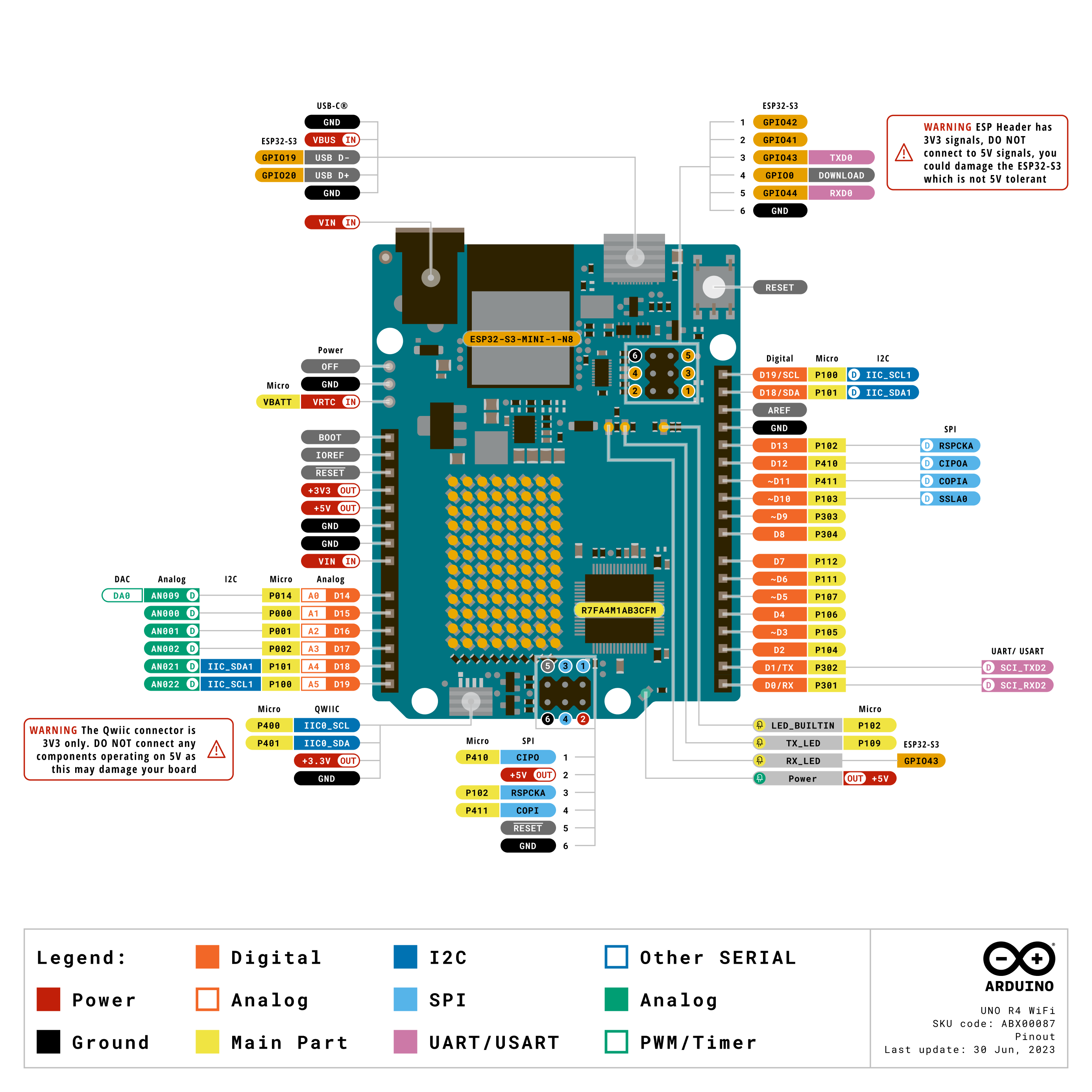
https://docs.arduino.cc/hardware/uno-r4-wifi
UNO R4 WiFi | Arduino Documentation
Here you will find the technical specifications for the Arduino® UNO R4 WiFi. Note on ESP header: the ESP32-S3 module on this board operates on 3.3 V. The ESP header located close to the USB-C® connector is 3.3V only and should not be connected to 5 V. T
docs.arduino.cc

| 네오픽셀 (0) | 2023.08.03 |
|---|---|
| Arduino Touch Sensor MPR121 (0) | 2023.08.02 |
| ESP32 VS ESP8266 (0) | 2023.07.27 |
| ESP32 제품 시리즈 비교 (0) | 2023.07.27 |
| ESP32 시리얼 모니터 반복 문자 출력 오류 (0) | 2023.07.14 |
https://makeradvisor.com/esp32-vs-esp8266/
ESP32 vs ESP8266 - Pros and Cons - Maker Advisor
In this post we’re going to do a comparison: ESP32 vs ESP8266. The ESP32 is much more powerful than the ESP8266, contains more GPIOs, faster Wi-Fi, and also supports Bluetooth.
makeradvisor.com
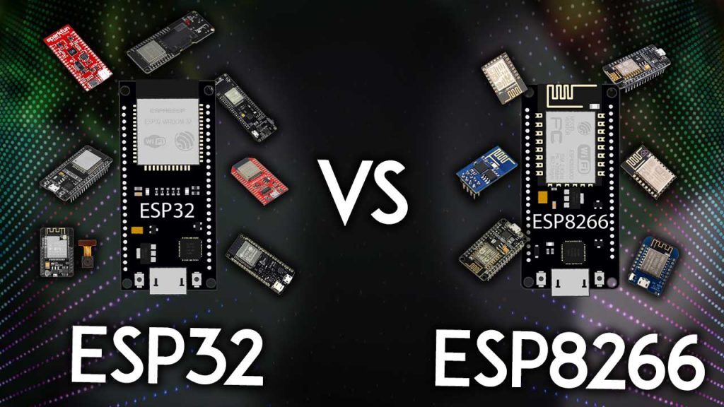
What’s the difference between ESP32 and ESP8266? Should you use the ESP32 or the ESP8266 in your projects? In this article, we’ll compare the ESP32 with the ESP8266 and cover the pros and cons of each board.
The ESP32 and ESP8266 are cheap Wi-Fi modules perfectly suited for DIY projects in the Internet of Things (IoT) and Home Automation fields.
Both chips have a 32-bit processor. The ESP32 is a dual-core 160MHz to 240MHz CPU, whereas the ESP8266 is a single-core processor that runs at 80MHz.
These modules come with GPIOs that support various protocols like SPI, I2C, UART, ADC, DAC, and PWM. The best part is that these boards come with wireless networking included, which makes them apart from other microcontrollers like the Arduino. This means that you can easily control and monitor devices remotely via Wi-Fi or Bluetooth (in the case of ESP32) for a very low price.
Alternatively, if you don’t need to use its wireless capabilities, you can use the ESP32/ESP8266 to control inputs and outputs as you would do with an Arduino. However, you should take into account that whereas the Arduino works with 5V logic, the ESP32 and ESP8266 work at 3.3V.
The ESP32 is the ESP8266 successor. It adds an extra CPU core, faster Wi-Fi, more GPIOs, and supports Bluetooth 4.2 and Bluetooth low energy. Additionally, the ESP32 comes with touch-sensitive pins that can be used to wake up the ESP32 from deep sleep, a built-in hall effect sensor, and a built-in temperature sensor (recent versions of the ESP32 don’t come with a built-in temperature sensor anymore).
Both boards are cheap, but the ESP32 costs slightly more. While the ESP32 can cost around $6 to $12, the ESP8266 can cost $4 to $6 (but it really depends on where you get them and what model you’re buying).
The following table shows the main differences between the ESP8266 and the ESP32 chips (table adapted from AMICA_IO).
ESP8266ESP32
|
|
ESP8266
|
ESP32
|
|
|
 |
 |
|
MCU
|
Xtensa Single-core 32-bit L106
|
Xtensa Dual-Core 32-bit LX6 with 600 DMIPS
|
|
802.11 b/g/n Wi-Fi
|
HT20
|
HT40
|
|
Bluetooth
|
X
|
Bluetooth 4.2 and BLE
|
|
Typical Frequency
|
80 MHz
|
160 MHz
|
|
SRAM
|
X
|
✓
|
|
Flash
|
X
|
✓
|
|
GPIO
|
17
|
34
|
|
Hardware /Software PWM
|
None / 8 channels
|
None / 16 channels
|
|
SPI/I2C/I2S/UART
|
2/1/2/2
|
4/2/2/2
|
|
ADC
|
10-bit
|
12-bit
|
|
CAN
|
X
|
✓
|
|
Ethernet MAC Interface
|
X
|
✓
|
|
Touch Sensor
|
X
|
✓
|
|
Temperature Sensor
|
X
|
✓(old versions)
|
|
Hall effect sensor
|
X
|
✓
|
|
Working Temperature
|
-40ºC to 125ºC
|
-40ºC to 125ºC
|
|
Price
|
$ (3$ - $6)
|
$$ ($6 - $12)
|
|
Where to buy
|
Best ESP8266 Wi-Fi Development Boards
|
ESP32 Development Boards Review and Comparison
|
Using ESP32 or ESP8266 bare chips is not easy or practical, especially when testing and prototyping. Most of the time, you’ll want to use ESP32 and ESP8266 development boards. These boards come with all the needed circuitry to power the chip, connect it to your computer, a circuit to upload code easily, pins to connect peripherals, built-in power and control LEDs, and other useful features.
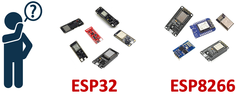
The ESP32 and ESP8266 development boards we use more often are the ESP32 DEVKIT DOIT Development board and the ESP8266 ESP-12E NodeMCU Kit and these are the ones we recommend for beginners. However, there are many other models of development boards that you can choose from. We recommend that you read the following guides:
The ESP32 has more GPIOs than the ESP8266, and you can decide which pins are UART, I2C, SPI—you need to set that on the code. This is possible due to the ESP32 chip’s multiplexing feature that allows you to assign multiple functions to the same pin.
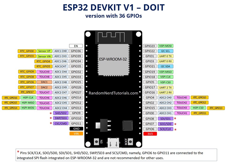
If you don’t set them on the code, they will be on the pins defined by default, as shown in the following figure (this is an example for the ESP32 DEVKIT V1 DOIT board (version with 36 GPIOS)—the pin location can change depending on the manufacturer).
To learn more about the ESP32 GPIOs and how to use them, read:
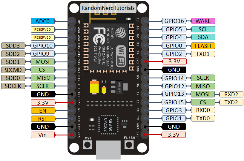
For means of comparison, here’s the pinout diagram for the ESP8266 ESP-12E NodeMCU Kit.
To learn more about the ESP8266 GPIOs and how to use them, read:
You can set PWM signals in any GPIO with configurable frequencies and duty cycle set on the code.
When it comes to the analog pins, these are static, but the ESP32 supports measurements on 18 channels (analog-enabled pins) versus just one 10-bit ADC pin on the ESP8266. The ESP32 also supports two 8-bit DAC channels.
Moreover, the ESP32 contains 10 capacitive sensing GPIOs, that detect touch and can be used to trigger events, or wake-up the ESP32 from deep sleep, for example.
The ESP32 supports Bluetooth communication protocol by default, while the ESP8266 doesn’t.
There are many ways to program the ESP32 and ESP8266 boards. Both boards can be programmed with the Arduino core using the Arduino IDE or other IDEs (like VS Code with the PlatformIO extension).

These are good news, especially for those used to program the Arduino board and are familiar with the Arduino “programming language”.
Getting started with the ESP32 or ESP8266 using Arduino IDE and have your first project running is very simple. You can follow these guides:
Although you can program both boards using Arduino IDE, they might not be compatible with the same libraries and functions. Some libraries are just compatible with one of the boards. This means that most of the time, your ESP8266 code will not be compatible with the ESP32. However, usually, you need to make a few modifications.
We have a dedicated list of free tutorials and projects for the ESP32 and ESP8266 boards using the Arduino IDE that you might found useful:
Another popular way of programming the ESP32 and ESP8266 boards is using MicroPython firmware.

MicroPython is a re-implementation of Python 3 targeted for microcontrollers and embedded systems. MicroPython is very similar with regular Python. So, if you already know how to program in Python, you also know how to program in MicroPython.
In MicroPython, most Python scripts are compatible with both boards (unlike when using Arduino IDE). This means that most of the time, you can use the same script for ESP32 and ESP8266.
You can get started with MicroPython firmware on the ESP32 and ESP8266 very quickly by following our free guides:
We also have a list of free projects using MicroPython with the ESP32 and ESP8266 boards:
If you want to get started with the ESP32 or ESP8266, you can take a look at our courses and projects:
So, at this point you may be wondering: Should I get an ESP8266 or an ESP32?
It really depends on what you want to do. There is space for both boards, and both have pros and cons.
The ESP8266 is cheaper than the ESP32. Although it doesn’t have as many functionalities, it works just fine for most simple DIY IoT projects. However, it has some limitations in the GPIO mapping, and it might not have enough pins for what you intend to do. If that’s the case, you should get an ESP32.
The ESP32 is much more powerful than the ESP8266, comes with more GPIOs with multiple functions, faster Wi-Fi, and supports Bluetooth. However, many people think that the ESP32 is more difficult to deal with than the ESP8266 because it is more complex. On the contrary, in our opinion, it is as easy to program the ESP32 as the ESP8266, especially if you intend to program it using the “Arduino language” or MicroPython.
The ESP32 has some cons too. The ESP32 is more expensive than the ESP8266. So, if you’re building a simple IoT project, the ESP8266 might do the trick for a lower price. Additionally, because the ESP8266 is “older” than the ESP32, some libraries and features are better developed for the ESP8266, and you’ll find more resources (forums, people with the same issues, and how to solve them, etc.). However, as time goes by, the ESP32 is being widely adopted, and these differences in terms of development and libraries won’t be noticeable.
My personal experience: in 2021, I use almost exclusively the ESP32 for IoT projects. It is more versatile, and it comes with much more functionalities like Bluetooth, different wake-up sources, many peripherals, and much more. Additionally, the price difference is not a big deal, in my opinion. Once you move to the ESP32, you won’t want to go back to the ESP8266.
We hope you’ve found our analysis ESP32 vs ESP8266 useful.
Just to wrap up the main differences between the ESP32 and ESP8266:
You might like reading the following ESP8266 and ESP32 related articles to have an idea of the selection of the most popular ESP32 and ESP8266 development boards:
So, if you’re a beginner, should you get started with the ESP32 or the ESP8266? At this point, we definitely recommend getting started with the ESP32 instead of the ESP8266. However, if you already have an ESP8266 board, you can get started with that board and then make the shift to the ESP32.
We have a vast selection of projects with these boards in the Random Nerd Tutorials blog to help you get started:
Thanks for reading.
| Arduino Touch Sensor MPR121 (0) | 2023.08.02 |
|---|---|
| NEW Arduino Uno R4 Boards - Minima & WiFi / 아두이노 우노 R4 미니머 & 와이파이 (0) | 2023.07.31 |
| ESP32 제품 시리즈 비교 (0) | 2023.07.27 |
| ESP32 시리얼 모니터 반복 문자 출력 오류 (0) | 2023.07.14 |
| ESP32 CAM (0) | 2023.07.01 |
| Feature | ESP32 Series | ESP32-S2 Series | ESP32-C3 Series | ESP32-S3 Series |
| Launch year | 2016 | 2020 | 2020 | 2020 |
| Core | Xtensa® dual-/single core 32-bit LX6 | Xtensa® single-core 32-bit LX7 | 32-bit single-core RISC-V | Xtensa® dual-core 32-bit LX7 |
| Wi-Fi protocols | 802.11 b/g/n, 2.4 GHz | 802.11 b/g/n, 2.4 GHz | 802.11 b/g/n, 2.4 GHz | 802.11 b/g/n, 2.4 GHz |
| Bluetooth® | Bluetooth v4.2 BR/EDR and Bluetooth Low Energy | ✖️ | Bluetooth 5.0 | Bluetooth 5.0 |
| Typical frequency | 240 MHz (160 MHz for ESP32-S0WD) | 240 MHz | 160 MHz | 240 MHz |
| SRAM | 520 KB | 320 KB | 400 KB | 512 KB |
| ROM | 448 KB for booting and core functions | 128 KB for booting and core functions | 384 KB for booting and core functions | 384 KB for booting and core functions |
| Embedded flash | 2 MB, 4 MB, or none, depending on variants | 2 MB, 4 MB, or none, depending on variants | 4 MB or none, depending on variants | 8 MB or none, depending on variants |
| External flash | Up to 16 MB device, address 11 MB + 248 KB each time | Up to 1 GB device, address 11.5 MB each time | Up to 16 MB device, address 8 MB each time | Up to 1 GB device, address 32 MB each time |
| External RAM | Up to 8 MB device, address 4 MB each time | Up to 1 GB device, address 11.5 MB each time | ✖️ | Up to 1 GB device, address 32 MB each time |
| Cache | ✔️ Two-way set associative | ✔️ Four-way set associative, independent instruction cache and data cache | ✔️ Eight-way set associative, 32-bit data/instruction bus width | ✔️ Four-way or eight-way set associative for instruction cache; four-way set associative for data cache, 32-bit data/instruction bus width |
| Peripherals | ||||
| ADC | Two 12-bit, 18 channels | Two 12-bit, 20 channels | Two 12-bit SAR ADCs, at most 6 channels | Two 12-bit SAR ADCs, 20 channels |
| DAC | Two 8-bit channels | Two 8-bit channels | ✖️ | ✖️ |
| Timers | Four 64-bit general-purpose timers, and three watchdog timers | Four 64-bit general-purpose timers, and three watchdog timers | Two 54-bit general-purpose timers, and three watchdog timers | Four 54-bit general-purpose timers, and three watchdog timers |
| Temperature sensor | ✖️ | 1 | 1 | 1 |
| Touch sensor | 10 | 14 | ✖️ | 14 |
| Hall sensor | 1 | ✖️ | ✖️ | ✖️ |
| GPIO | 34 | 43 | 22 | 45 |
| SPI | 4 | 4 | 3 | 4 |
| LCD interface | 1 | 1 | ✖️ | 1 |
| UART | 3 | 2 1 | 2 1 | 3 |
| I2C | 2 | 2 | 1 | 2 |
| I2S | 2, can be configured to operate with 8/16/32/40/48-bit resolution as an input or output channel. | 1, can be configured to operate with 8/16/24/32/48/64-bit resolution as an input or output channel. | 1, can be configured to operate with 8/16/24/32-bit resolution as an input or output channel. | 2, can be configured to operate with 8/16/24/32-bit resolution as an input or output channel. |
| Camera interface | 1 | 1 | ✖️ | 1 |
| DMA | Dedicated DMA to UART, SPI, I2S, SDIO slave, SD/MMC host, EMAC, BT, and Wi-Fi | Dedicated DMA to UART, SPI, AES, SHA, I2S, and ADC Controller | General-purpose, 3 TX channels, 3 RX channels | General-purpose, 5 TX channels, 5 RX channels |
| RMT | 8 channels | 4 channels 1, can be configured to TX/RX channels | 4 channels 2, 2 TX channels, 2 RX channels | 8 channels 2, 4 TX channels, 4 RX channels |
| Pulse counter | 8 channels | 4 channels 1 | ✖️ | 4 channels 1 |
| LED PWM | 16 channels | 8 channels 1 | 6 channels 2 | 8 channels 1 |
| MCPWM | 2, six PWM outputs | ✖️ | ✖️ | 2, six PWM outputs |
| USB OTG | ✖️ | 1 | ✖️ | 1 |
| TWAI® controller (compatible with ISO 11898-1) | 1 | 1 | 1 | 1 |
| SD/SDIO/MMC host controller | 1 | ✖️ | ✖️ | 1 |
| SDIO slave controller | 1 | ✖️ | ✖️ | ✖️ |
| Ethernet MAC | 1 | ✖️ | ✖️ | ✖️ |
| ULP | ULP FSM | PicoRV32 core with 8 KB SRAM, ULP FSM | ✖️ | PicoRV32 core with 8 KB SRAM, ULP FSM |
| Debug Assist | ✖️ | ✖️ | 1 | ✖️ |
| Security | ||||
| Secure boot | ✔️ | ✔️ Faster and safer, compared with ESP32 | ✔️ Faster and safer, compared with ESP32 | ✔️ Faster and safer, compared with ESP32 |
| Flash encryption | ✔️ | ✔️ Support for PSRAM encryption. Safer, compared with ESP32 | ✔️ Safer, compared with ESP32 | ✔️ Support for PSRAM encryption. Safer, compared with ESP32 |
| OTP | 1024-bit | 4096-bit | 4096-bit | 4096-bit |
| AES | ✔️ AES-128, AES-192, AES-256 (FIPS PUB 197) | ✔️ AES-128, AES-192, AES-256 (FIPS PUB 197); DMA support | ✔️ AES-128, AES-256 (FIPS PUB 197); DMA support | ✔️ AES-128, AES-256 (FIPS PUB 197); DMA support |
| HASH | SHA-1, SHA-256, SHA-384, SHA-512 (FIPS PUB 180-4) | SHA-1, SHA-224, SHA-256, SHA-384, SHA-512, SHA-512/224, SHA-512/256, SHA-512/t (FIPS PUB 180-4); DMA support | SHA-1, SHA-224, SHA-256 (FIPS PUB 180-4); DMA support | SHA-1, SHA-224, SHA-256, SHA-384, SHA-512, SHA-512/224, SHA-512/256, SHA-512/t (FIPS PUB 180-4); DMA support |
| RSA | Up to 4096 bits | Up to 4096 bits | Up to 3072 bits | Up to 4096 bits |
| RNG | ✔️ | ✔️ | ✔️ | ✔️ |
| HMAC | ✖️ | ✔️ | ✔️ | ✔️ |
| Digital signature | ✖️ | ✔️ | ✔️ | ✔️ |
| XTS | ✖️ | ✔️ XTS-AES-128, XTS-AES-256 | ✔️ XTS-AES-128 | ✔️ XTS-AES-128, XTS-AES-256 |
| Other | ||||
| Deep-sleep (ULP sensor-monitored pattern) | 100 μA (when ADC work with a duty cycle of 1%) | 22 μA (when touch sensors work with a duty cycle of 1%) | No such pattern | TBD |
| Size | QFN48 5*5, 6*6, depending on variants | QFN56 7*7 | QFN32 5*5 | QFN56 7*7 |
https://products.espressif.com/#/product-selector?names=
ESP Product Selector
products.espressif.com
| NEW Arduino Uno R4 Boards - Minima & WiFi / 아두이노 우노 R4 미니머 & 와이파이 (0) | 2023.07.31 |
|---|---|
| ESP32 VS ESP8266 (0) | 2023.07.27 |
| ESP32 시리얼 모니터 반복 문자 출력 오류 (0) | 2023.07.14 |
| ESP32 CAM (0) | 2023.07.01 |
| ESP32 Apple homekit (0) | 2023.06.30 |
#include <iostream>

using std::cout;
using std::cin;
using std::endl;


class Time {
public:
	Time() :h(0), m(0), s(0) {}

	Time(int s_) :Time() {
		s = s_;
	}

	Time(int m_, int s_) :Time(s_) {
		m = m_;
	}

	Time(int h_, int m_, int s_) : Time(m_, s_) {
		h = h_;
	}

//private:
	int h;
	int m;
	int s;
};


int main()
{
	Time t1;
	Time t2(5);
	Time t3(3, 16);
	Time t4(10, 20, 15);

	cout << "t1 : " << t1.h << " : " << t1.m << " : " << t1.s << endl;
	cout << "t2 : " << t2.h << " : " << t2.m << " : " << t2.s << endl;
	cout << "t3 : " << t3.h << " : " << t3.m << " : " << t3.s << endl;
	cout << "t4 : " << t4.h << " : " << t4.m << " : " << t4.s << endl;
}t1 : 0 : 0 : 0
t2 : 0 : 0 : 5
t3 : 0 : 3 : 16
t4 : 10 : 20 : 15
| C,C++ : 구조체 만들기(struct) (0) | 2023.07.31 |
|---|---|
| C,C++ : typedef 자료형에(구조체) 새 이름(별명) (0) | 2023.07.31 |
| C/C++ 초기화 (0) | 2023.07.26 |
| C,C++: 글래스 구초체 (0) | 2023.07.26 |
| C,C++ : using, namespace(std::cout,std::endl) (0) | 2023.07.19 |
class Complex
{
public:
	Complex()
	{
		real = 0;
		imag = 0;
	}

private:
	double real;
	double imag;

};
class Complex
{
public:
Complex(): real(0),imag(0){}
private:
double real;
double imag;
};class Complex
{
public:
Complex(double real_= 0, double imag_= 0)
{
real = real_;
imag = imag_;
}
private:
double real;
double imag;
};class Complex
{
public:
Complex(double real_ = 0, double imag_ = 0) : real(real_),imag(imag_){}
private:
double real;
double imag;
};class Complex
{
public:
Complex(double real = 0, double imag = 0) : real(real), imag(imag) {}
private:
double real;
double imag;
};| C,C++ : typedef 자료형에(구조체) 새 이름(별명) (0) | 2023.07.31 |
|---|---|
| C,C++:생성자 위임 (0) | 2023.07.26 |
| C,C++: 글래스 구초체 (0) | 2023.07.26 |
| C,C++ : using, namespace(std::cout,std::endl) (0) | 2023.07.19 |
| C,C++ : 클래스 템플릿 리스트 구현 (0) | 2023.07.19 |
main.cpp
#include <iostream>

using std::cout;
using std::cin;
using std::endl;


class Complex
{
public:
	Complex()
	{
		real = 0;
		imag = 0;
	}
	Complex(double real_, double imag_)
	{
		real = real_;
		imag = imag_;
	}

	double GetReal()
	{
		return real;
	}

	void SetReal(double real_)
	{
		real = real_;
	}

	double GetImag()
	{
		return imag;
	}

	void SetImag(double imag_)
	{
		real = imag_;
	}

	~Complex()
	{

	}

private:
	double real;
	double imag;


};


int main()
{
	Complex c1;
	Complex c2 = Complex(2, 3);
	Complex c3(2, 3);
	Complex c4 = { 2,3 };

	cout << "c1 = "<< c1.GetReal() << ","<< c1.GetImag()<< endl;
	cout << "c2 = "<< c2.GetReal() << ","<< c2.GetImag()<< endl;
	cout << "c3 = "<< c3.GetReal() << ","<< c3.GetImag()<< endl;
}